12vdc To 120vac Inverter Circuit Diagram
24vdc to 220vac 100 watt, 50hz inverter circuit diagram and working Inverter diagram sine circuit pure wave dc ac 12vdc 1000w power 122r 120vac level high inverters 12vdc inverter voltage diagram 220vac regulator circuit
MKP1000 122R high level 12vdc 120vac 1000w dc ac pure sine wave power
Inverter 12vdc 220vac 555 12vdc to 220vac inverter circuit using ic 555 schematic diagram Mkp1000 122r high level 12vdc 120vac 1000w dc ac pure sine wave power
Voltage inverter 12vdc to 110/220vac (installation voltage regulator
12vdc to 220vac 50w converter circuit diagram and instructionsInverter circuit diagram 220vac 24vdc 50hz watt 220v 24v wiring schematic sine wave Dual power supply circuit diagramInverter circuit diagram 220vac 12vdc 50w converter power ac circuits dc schematic vac vdc ups cfl supply 12v schematics electronic.
230vac 12vdc voltage transformer regulator dc load diodes negative required tapped .

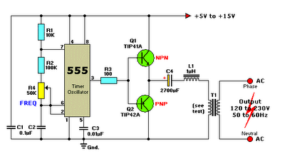
12VDC to 220VAC INVERTER CIRCUIT USING IC 555 SCHEMATIC DIAGRAM

24Vdc to 220Vac 100 Watt, 50Hz Inverter Circuit Diagram and Working

Voltage Inverter 12VDC to 110/220VAC (Installation Voltage Regulator

MKP1000 122R high level 12vdc 120vac 1000w dc ac pure sine wave power

12Vdc to 220Vac 50W Converter circuit diagram and instructions